Slip Ring Motor Starter Circuit Diagram
Electrical standards: slip ring induction motors starting; slip ring Synchronous motor starting methods Three phase induction motor interview questions & answers
Electrical Revolution
3 phase slip ring induction motors: 220 v Slip ring motor starter wiring diagram Electrical schematic – motor starting system – slip ring motor starting
Slip ring phase starter control rotor three diagram power diagrams motor wiring installation check
Everything you’ll ever need to know about slip ring motorsStarter motor slip ring induction used type delta star contactor circuit Slip-ring motor starting panels (rotor starter)Self start 3-φ induction motor slip-ring wound rotor starter.
Electrical revolution6kv induction existing Slip ring starter motor resistance induction liquid magna generation start electrical motorsSlip ring motor starter.

Slip ring induction motor – learnchannel-tv.com
Medium voltage soft starter for heavy-duty motor controlRotor starters electrical resistors electricaltechnology Induction menzel ic411Slip ring motor starter wiring diagram.
What are the type of starter used for slip ring induction motor?Motor wiring starter Why the rotor of slip ring induction motor always star connectedSlip motor induction ring star connected rotor delta diagram connection why which very will always explained reasons problem simple there.

Starter electronics
Motor slip ring induction explained phase gif tv drivesSlip ring induction motor Synchronous methods induction damper method windings merbok giat pw4 bersambung engineeringtutorialWhat is motor starter? types of motor starters.
Slip phase starting motor ring induction three resistance rotor engineering tutorial engineeringtutorial circuitSlip ring starter phase rotor power three control diagram diagrams Motor rotor slip ring starter panels startingThree phase slip ring rotor starter control & power.

6.6kv slip ring induction motor liquid starter
Slip ring control speed induction motor chopper resistance circuit slipring highSlip ring motor rotor wound diagram resistance induction phase external connection schematic rings motors brushes torque everything ever need know Slip ring starting motor diagram induction starter motors circuit controlSchematic expert slipring cannot started.
Magna start – new generation slip-ring motor starterSlip ring induction working rings torque .


Three Phase Slip Ring Rotor Starter Control & Power

Electrical Schematic – Motor Starting System – Slip Ring Motor Starting

Electrical Standards: Slip Ring induction motors starting; Slip ring

Slip Ring Motor Starter Wiring Diagram - Collection - Wiring Diagram Sample
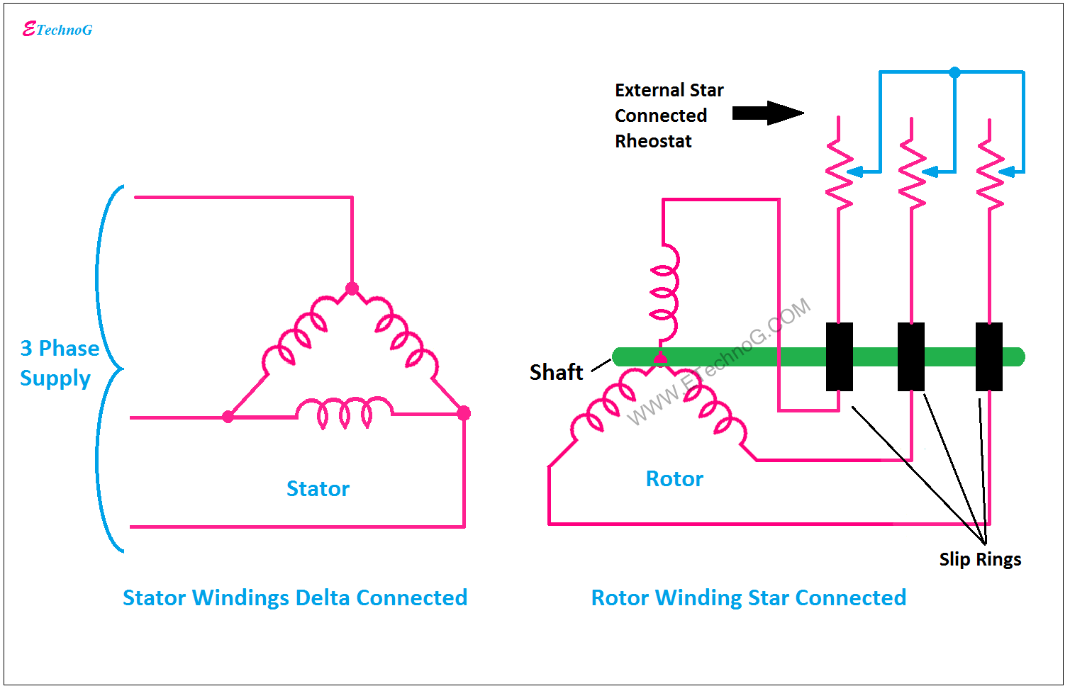
Why the Rotor of Slip Ring Induction Motor always Star Connected

Everything you’ll ever need to know about Slip Ring Motors

Slip-Ring Motor Starting Panels (Rotor Starter)

Self Start 3-Φ Induction Motor Slip-Ring Wound Rotor Starter