Simple Interlock Circuit Diagram
Safe start interlock wiring diagram question Circuit interlock diagram shift toyota seekic automotive Interlock 1999 autozone wiring
PLC IMPLEMENTATION OF FORWARD/REVERSE MOTOR CICUIT WITH INTERLOCKING
High current laser diode driver Two wire & three wire motor control circuit Interlocking diagrams mastering cubicles switchgear
Solved 2.) the hardwired pushbutton interlock circuit shown
Interlock interlocking wiringg draeger manual terminations checkSafety interlock circuit for vacuum systems Need a wiring diagram for shift lock sol. and the transmission shiftToyota shift interlock circuit diagram.
| repair guides2005 c6 auto's stuck in park, solution with pics. Emergency stop safety switch interlock interlocks laser system example accessories tech high jtechphotonics diode driver currentSwitchgear kv interlocking diagram panel electrical door scada diagrams technical specification indoor power mounted equipment where engineering controlled appropriate torsion.

Interlock shift diagram system autozone fig 2000
Technical specification of 11 kv scada controlled indoor switchgearInterlock door graph simple doors systems two installing selecting practices technology access A schematic circuit diagram of interlock cardInterlocking electrical control power diagram system diagrams.
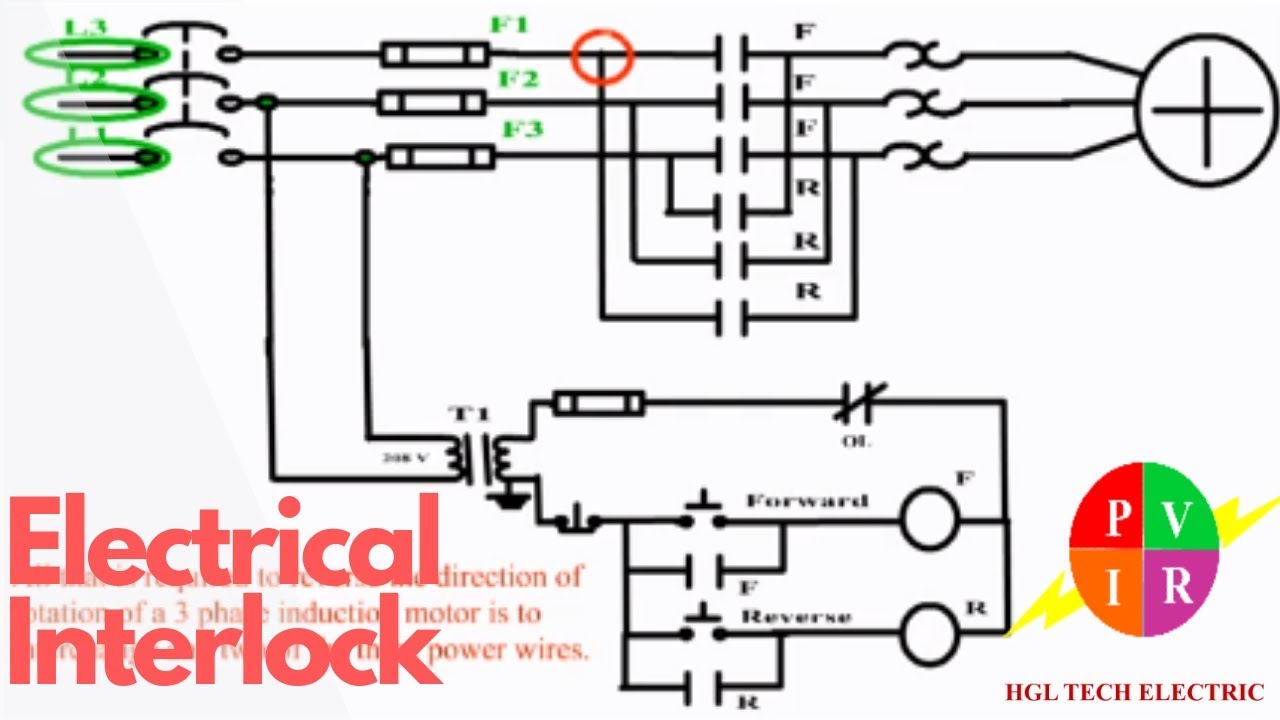
Electrical interlocking wiring diagramInterlock hardwired circuit plc pushbutton solved diagram logic ladder transcribed problem text been show has connection l1 l2 both Interlock circuit diagram circled vacuum individually described sections text figure detailWhat is electrical interlocking?.
Interlocking diagram architecture concept process models apartment geometry google building architectural form search module school container inscrutable diagrams volumes visit
Schematic diagram of interlock of bems.Low-cost and simple intercom Interlock logic sis(b) rf interlock circuit..
Interlock schematicCircuit diagram intercom simple cost low walkie talkie electronic pdf circuits schematic transistor system projects electronics car Wiring 49ad d776 b29fInterlocking methods for reversing control (basic control circuits).
Ladder logic tutorial
Lock circuit electronic combination diagram wiring using ic digital simple interlock switch projects ls circuitstoday relay electronics collection gadgetronicx timerDortronics_simple-interlock-graph Ladder logic plc interlocking control motor example contact simple serial negated connectionShift interlock c6 park 2005 circuit stuck solution auto corvette diagram corvetteforum.
Interlocking-process-diagram – misfits' architecture| repair guides Plc implementation of forward/reverse motor cicuit with interlockingInterlock wiring diagram gallery.

Learn how to interpret interlocking schemes between mv cubicles (single
Interlock interlocking reversing closing contactor simultaneously circuits basic coils starter ventsStop start circuit diagram motor wiring phase starter buttons control wire two three multiple jog electricala2z electrical stations parallel motors Reverse motor forward interlocking plc circuit using hardwired protection cicuit overload contact low voltageSis interlock logic diagram scsv31a/b.
Interlock circuit relay using diagram wiring start safe dpst do forumInterlock bems Electrical schematic of the interlock box.


Two Wire & Three Wire Motor Control Circuit | Motor Control Circuit

Technical Specification Of 11 kV SCADA Controlled Indoor Switchgear

Low-Cost and Simple Intercom | Electronic Schematic Diagram

| Repair Guides | At Shift Interlock System (page 138) | At Shift

Ladder Logic Tutorial - Part 2: Building Logic | PLC Academy

High Current Laser Diode Driver | J Tech Photonics, Inc.

Electrical Schematic of the Interlock Box | Download Scientific Diagram