Simple Esc Circuit Diagram
Schematic hall esc brushless circuit homemade diy cd sensored sensors Bec wiring 30a carvalho figure1 schematics stefanv circuits luiz Esc diagram pilot signal output input part works bec every parts has
What are the advantages of an ESC over a PWM? - Electrical Engineering
Esc scheme schematics adc problem board noisy ground too pcb electrical stack own made Schematic review for electronic speed controller (esc) : r Motor controller
Universal esc circuit for bldc motors
Wiring diagram brushless motor escEsc circuit diagram Rc esc speed electronic controller diy airplane control schematic advisor single electronics electric make power dictionary own wikipediaEsc brushless motor circuit dc drive bldc simple control controller speed electronic sensorless.
Brushless dc motor with esc and arduino unoEsc schematic adc circuit scheme problem bldc schematics Brushless circuit esc 48v schematic schematics 36v speed scooter makeblock 3phaseElectronic speed control (esc) : circuit, types, working & its applications.

Motor brushless dc algorithm startup circuit esc microcontroller diagram control speed code stack
Esc wiring diagram drone wires flexrc core assemble kit diy quadcopter adwords acquired according information fcEsc circuit bec eliminator equipped Drone esc wiring diagramCircuit motor control esc throttle board brushless speed schematics electronic pwm schematic diagram circuits bldc advantages over gr next electronics.
Schematic electronic speed esc controller review analog interface digital redditEsc bldc circuits opamp inverter oscillator electronic generators controller What are the advantages of an esc over a pwm?Esc sensored.

Sensorless brushless dc motor drive with an esc and pic16f887
Drone esc wiring diagramBrushless pwm Wiring diagram brushless motor escEsc circuit diagram.
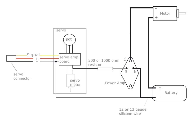
Sensored esc circuit homemade diyEsc part 1 – pilot Make your own sensored esc: 5 stepsEsc circuit diagram.

Esc power usb voltage options both input smooth output maybe actually don know good motor
Phase using circuit generator transistors signal bldc esc transistor circuits wave make sine homemade motors motor three driver mosfet simpleUniversal esc circuit for bldc and alternator motors Esc brushless circuitsBrushless schematic sensored arduino phase circuitos homemade.
Esc wiring diagram drone fc 1s 4a rc wire schematic motor control wires electronic speed escs 18awg came then power .


Esc Circuit Diagram | Read Wiring

schematics - ESC scheme ADC problem - Electrical Engineering Stack Exchange
ESC - Electronic Speed Control ~ Rc Dictionary

Sensored ESC circuit homemade DIY

Universal ESC Circuit for BLDC motors

microcontroller - Brushless DC Motor - Sensoreless Startup Algorithm

Electronic Speed Control (ESC) : Circuit, Types, Working & Its Applications

motor controller - Both USB and ESC power options - Electrical